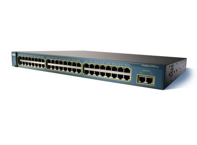
Cisco 2950 Series Switches – Specifications/Features/LEDs and half Numbers

Information:
Information required on Cisco Catalyst 2950 Series Switches LEDs and half Numbers.
Details:
Cisco 2950 Series Switch Hardware Specifications, Features, LEDs and half Numbers.
Catalyst 2950 Series Switch Hardware Overview:
Features:
The Catalyst 2950 switches are a family of local area network switches that end-users will use to attach workstations. Different network devices, corresponding to servers, routers, and other switches. All models of the switch are cluster-capable, however just some models are stackable. End-users can use switches with gigabit interface device module slots to create switch stacks by victimising Gigastack GBICs. Some switch models will be deployed as backbone switches, aggregating one0BASE-T, 100BASE-TX, Gigabit local area network and Long-Reach local area network traffic from different switches and network devices. See the switch package configuration guide for examples that show. However, the end-user would possibly deploy the switches in the end-user network.
These are the switch features:
-
Hardware:
- Catalyst 2950-12 switch 12 10/100 local area network ports.
- Catalyst 2950-24 switch 24 10/100 local area network ports.
- Catalyst 2950C-24 switches 24 10/100 Ethernet ports and a pair of 100BASE-FX ports.
- Catalyst 2950G-12-EI 12 10/100 Ethernet ports and a pair of GBIC module slots.
- Catalyst 2950G-24-EI 24 10/100 local area network ports and 2 GBIC module slots.
- Catalyst 2950G-24-EI-DC 24 10/100 local area network ports and 2 GBIC module slots with DC-input power.
- Catalyst 2950G-48-EI 48 10/100 local area network ports and 2 GBIC module slots.
Cisco 2950 ST-8 LRE switches 8 LRE ports, 2 10/100/1000 local area network ports, and 2 small-form-factor pluggable module slots. Catalyst 2950 ST-24 LRE switches 24 LRE ports, 2 10/100/1000 local area network ports, and 2 SFP module slots.
Cisco 2950 ST-24 LRE 997 switches 24 LRE ports, 2 ten/100/1000 local area network ports, and a pair of SFP module slots with DC-input power.
Configuration:
Once the switch is running at one thousand Mb/s, it supports only full-duplex mode.
For 1000BASE-SX ports, supports solely 1000-Mb/s Associate in Nursing full-duplex settings.
Supports 8192 raincoat addresses:
Checks for errors on a received packet, determines the destination port, stores the packet in shared memory, and so forwards the packet to the destination port.
-
Power redundancy:
Association for an ex gratia Cisco RPS three hundred redundant power grid That uses AC input and provides DC output to the switch.
Association for an optional Cisco RPS 675 that uses AC input and supplies DC output to the switch.
Bound Cisco LRE client premises instrumentation devices aren’t supported by certain Catalyst 2950 LRE switches. In Table 1-1, affirmative implies that the CPE is supported by the switch; No means that the CPE isn’t supported by the switch.
Front-Panel Description:
The switch front panel contains the ports, the LEDs and Mode button.
Nevertheless, the Catalyst 2950ST-24 LRE 997 switch, the front panel of the Catalyst 2950 LRE switches also contain the console port and AC power instrumentation. On the Catalyst 2950ST-24 LRE 997 switch, the front panel contains a DC power connector, a DC ground lug, and an RJ-45 console port.
For additional Information concerning the facility connectors on the LRE switches, see the “Power Connectors” section.
The ports will hook up with these devices:
10BASE-T devices, corresponding to workstations and hubs, through commonplace RJ-45 connectors and 2 twisted-pair cabling. The end-user can use class 3, 4, or five cabling.
100BASE-TX devices, such as high-speed workstations, servers, hubs, routers, and different switches, through standard RJ-45 connectors and two or four twisted-pair, class 5 cabling.
The ten/100 ports will be expressly set to control in any combination of 0.5 duplex, full duplex, 10 Mb/s, or a hundred Mb/s. Once set for autonegotiation, a port senses the speed and duplex settings of the attached device and advertises its own capabilities. If the attached device supports auto negotiation, the port negotiates the most effective association and configures itself accordingly.
-
10/100/1000 Ports:
The ports will hook up with these devices:
- 10BASE-T devices, corresponding to workstations and hubs, through commonplace RJ-45 connectors and 2 or four twisted-pair, class five cabling.
- 100BASE-TX devices, such as high-speed workstations, servers, hubs, routers, and different switches, through standard RJ-45 connectors and two or four twisted-pair, class 5 cabling.
- 1000BASE-T devices, such as high-speed workstations, servers, hubs, routers, and different switches, through commonplace RJ-45 connectors and 4 twisted-pair, class five cabling.
- The 10/100/1000 ports on the Catalyst 2950T-48-SI and Catalyst 2950 LRE switches can be explicitly set to operate at 10 or 100 Mb/s in full- or half-duplex mode or at 1000 Mb/s in full-duplex mode.
- Among each logical port, the end-user can use solely the copper or the fibre optic port at one time.
-
LRE Port:
The LRE port uses one RJ-21 instrumentation to attach up to twenty four Cisco LRE CPE devices through structured or unstructured wiring, corresponding to existing phone lines.
bound Catalyst 2950 LRE switches support certain Cisco LRE CPE devices. The LRE switches support which CPE devices.
End-user can connect the Cisco 575 LRE CPE and Cisco 585 LRE CPE devices to LRE ports on an equivalent Catalyst 2950 ST-8 LRE or 2950ST-24 LRE switch.
The default mode for every LRE port is speed auto sensing Associate in Nursing half-duplex operation. For Information concerning configuring the LRE ports, see the switch package configuration guide.
If phone services, corresponding to voice or an Integrated Services Digital Network, use an equivalent cabling as LRE traffic. If the opposite telephone services are connected through a PBX switch, a non-homologated POTS splitter, corresponding to the Cisco LRE forty eight POTS Splitter, will be used. The PBX routes voice traffic to non-public telephone networks and also the PSTN. For additional Information concerning the Cisco LRE 48 POTS Splitter, see the Installation and pledge Notes for the Cisco LRE 48 POTS Splitter.
- If the installation doesn’t have a PBX, a certified, homologated POTS splitter is needed to attach on to the PSTN.
- If an association to a telephone network isn’t required, a splitter isn’t needed, and also the switch will connect on to the patch panel.
- For additional Information concerning the Cisco LRE CPE devices, see the Cisco LRE CPE Hardware Installation Guide.
-
GBIC Module Ports:
The GBIC module slots support these modules:
- 1000BASE-SX GBIC module for fibre-optic connections that can’t exceed 1804 feet.
- 1000BASE-LX/LH GBIC module for fibre-optic connections that cannot exceed 32,810 feet.
- 1000BASE-ZX GBIC module for fibre-optic connections that cannot exceed 328,100 feet.
- CWDM GBIC module for single-mode fiber-optic associations that can’t exceed three 93,719 feet.
- GigaStack GBIC module for making a 1-Gb/s stack configuration of up to 9 supported switches.
Also read:


